Search filter
141 results found
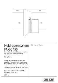
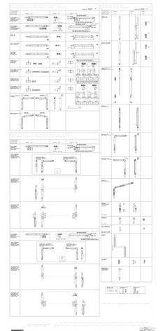
Wiring diagram FA CG 150
… Wiring diagram GEZE hold-open system FA GC 150 Contents … Wiring diagram … 36 Wireless ceiling-mounted detector GC 172 or GC 173 – manual trigger switch or fire detector contact wired … .13 Wireless ceiling-mounted detector wired – wireless input modules GC 175 … Wiring diagram úú úú úú úú úú úú úú úú … Wiring diagram Note the requirements for selection and installation of the fire detectors and manual trigger switches in chapter … 29 Wiring diagram … 30 GEZE hold-open system FA GC 150 German institute for construction technology Wiring diagram Ceiling-mounted detectors GC 152 and GC 153 with line monitoring The general construction technique permit requires the cable to the ceiling-mounted detectors to be monitored. Line monitoring is active if: úú jumper J3 of the lintel-mounted smoke switch to the measuring chamber is set (2-3 factory setting, see chap. … 31 Wiring diagram GEZE hold-open system FA GC 150 Connection of a ceiling-mounted thermal detector GC 153 as a lintel-mounted detector and two further ceiling-mounted detectors PLEASE NOTE When two floor springs TS 550 E are used, no more than two ceiling-mounted detectors may be connected. … .2 Wiring diagram Ceiling-mounted smoke detector ORS 142 The ceiling-mounted detector ORS 142 is made up of the smoke detector ORS 142 and the base ORS 143 A. Ceiling-mounted smoke detector kit ORS 142 with úú … 33 Wiring diagram … .2 Wiring diagram Contact to the fire alarm system XX When a potential-free contact of the fire alarm system is connected, remove jumper J1 from the lintel-mounted smoke switch. Line monitoring is active if: úú jumper J3 of the lintel-mounted smoke switch to the measuring chamber is set (2-3, see chap. … The cable to the potential-free contact (fire-alarm system) must be laid separately or protected. 35 Wiring diagram … Wireless ceiling-mounted detector wired – wireless input modules GC 175 … .3 Wireless ceiling-mounted detector GC 172 or GC 173 – manual trigger switch or fire detector contact wired … .2 Wiring diagram GEZE hold-open system FA GC 150 Fig. … m 37 Wiring diagram … .3 German institute for construction technology Wiring diagram Contact of the fire alarm system and manual trigger switch UTA The general construction technique permit requires line monitoring to the potential-free contact of the fire alarm system and to the manual trigger switch. Line monitoring is active if: úú a … ), úú a 43 kΩ resistor is connected in parallel at both lintel-mounted smoke switches directly at the alarm output. 39 Wiring diagram GEZE hold-open system FA GC 150 … 40 GEZE hold-open system FA GC 150 Wiring diagram Door closer TS 4000 E-IS Door leaf installation úú Connector box with plug-in drip loop, ID 052105 GC 151 Connector box TS 4000 E-IS Door transmission Active leaf … 41 Wiring diagram GEZE hold-open system FA GC 150 E-ISM guide rail, E-ISM guide rail Boxer (E-ISM/G no hold-open function in the passive leaf, E-ISM/S no hold-open function in the active leaf) Connection board active leaf E hold-open device active leaf … 42 GEZE hold-open system FA GC 150 Wiring diagram Transom installation … 43 Wiring diagram GEZE hold-open system FA GC 150 Floor spring TS 550 E-IS úú Connection PCB, ID 001102 úú Terminal box on site Active leaf Passive leaf 24 VDC±10% Rem. w <20% 24 VDC±10% Rem. w <20% I=100 mA I=100 mA Switch closed if active leaf open Terminal box Connection board … GEZE hold-open system FA GC 150 Wiring diagram Hydraulic swing door drive TSA 160 NT F*, TSA 160 NT F EN7* Accessories TSA 160 NT F, ID 019654 Follow the wiring diagram for the TSA 160 NT swing door drive. … Hydraulic swing door drive TSA 160 NT F-IS* Accessories TSA 160 NT F, ID 019654 Follow the wiring diagram for the TSA 160 NT swing door drive. … 45 Wiring diagram GEZE hold-open system FA GC 150 Electromechanical swing door drive Slimdrive EMD F* Follow wiring diagram for the Slimdrive EMD swing door drive. … Electromechanical swing door drive Slimdrive EMD F-IS* Follow wiring diagram for the Slimdrive EMD swing door drive. … GEZE hold-open system FA GC 150 Wiring diagram Electromechanical swing door drive Powerturn F* Follow wiring diagram for the Powerturn swing door drive. … Follow wiring diagram for the Powerturn swing door drive. … 47 Wiring diagram GEZE hold-open system FA GC 150 Electromechanical swing door drive Powerturn F-IS/TS* Follow wiring diagram for the Powerturn swing door drive. … .4 Wiring diagram Hold-open system TS 5000 R Fig. … 49 Wiring diagram … GEZE hold-open system FA GC 150 Hold-open system Slimdrive EMD F/R Follow wiring diagram for the Slimdrive EMD swing door drive. … .9 Wiring diagram Fig. … 51 Wiring diagram GEZE hold-open system FA GC 150 … .10 Hold-open system Slimdrive EMD F/R-IS* Follow wiring diagram for the Slimdrive EMD swing door drive. 55 24 V … .11 Hold-open system Powerturn F/R* Follow wiring diagram for the Powerturn swing door drive. 55 24 V … GEZE hold-open system FA GC 150 Wiring diagram … .12 Hold-open system Powerturn F/R-IS* Follow wiring diagram for the Powerturn swing door drive. 55 24 V … 53 Wiring diagram GEZE hold-open system FA GC 150 … .13 Hold-open system Powerturn F/R-IS/TS* Follow wiring diagram for the Powerturn swing door drive. 24 V
(PDF | 11 MB)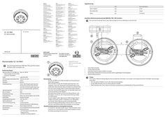
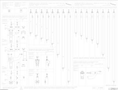
Wiring diagram heat detector GC 163 RWA
… wiring diagram) Smoke detector connection Test Use heat detector testing device from a recognised manufacturer for testing in accordance with the manufacturer’s instructions. àà The red LED on the detector must change to the alarm state. àà An alarm must be activated on the RWA control unit. àà After the test has been completed, reset the alarm on the control unit and carry out a detector line reset.
(PDF | 5 MB)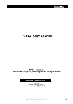
Additional wiring diagram TSA 160 NT TANDEM
… diagram applies in addition to connection diagram DCU5, Mat. No. 125014. Two drives TSA 160 NT are mechanically connected to form a tandem drive. The safety and actuation units must be connected at the DCU5 Master Control unit. The DCU5 control units can be configured with the buttons S1 and S2 or by using the Display program switch. Configuration at the Master- und Slave-control unit: DCU5 Master DCU5 Slave EF = 01 SI = according to desired function SO = 01 TE = depending on the used sensor EF = 02 SI = 00 SO = 01 TE = 00
(PDF | 135 KB)
Wiring diagram GC lock SHEV

Block diagram OL 320
(DWG | 1 MB)
Block diagram OL 90 N
(PDF | 557 KB)
Block diagram E 250 NT
(DWG | 1 MB)
Block diagram E 250 NT
(PDF | 435 KB)
Block diagram OL 90 N
(DWG | 1 MB)
Block diagrams ECchain
(DWG | 1 MB)